
August 2009 - After much cogitation, I've finally settled on a design for the brakes. Not only have I settled on a design, but I've done the first bit of work as well.
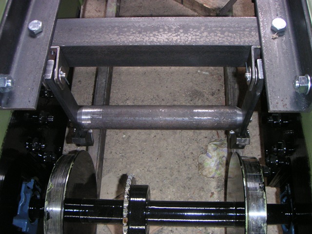
First part of brake system.
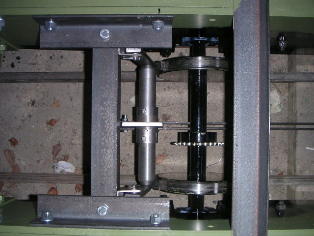
The frame is 50 x 50 x 6 angle, the brake hangers are 30 x 10 flat, each hanger is attached to the frame with a clevis pin through a butchered piece of 50 x 25 rectangular hollow section. The cross beam is 40mm round bar, tapered down to 30 mm at the ends, and bolted to the hangers with 8mm bolts. The brake shoes are cast iron, from The Engineer's Emporium, attached to the hangers with clevis pins.
Close up of brakes.
Brakes in the 'on' position.
October 2009 - Now have what seems to be a working brake system (plans are in hand for some more rigorous testing). At the driver's end (No.2 end) of the loco, a crank is pivoted on the cross beam which connects the two brake hangers. The short vertical arm of the crank is connected via brake rigging to a bracket which sits on the cross beam at the No.1 end. When the long horizontal arm of the crank is pulled up, the crank pulls on the brake rigging so applying the brakes at the No.1 end, and because the crank is pivoted on the No.2 end cross beam this also applies the brakes at the No.2 end.
The crank was cut from some 10mm plate, and pressed onto a piece of 50mm round bar with a hole bored in it to form a sliding fit over the cross beam. The crank is held laterally on the cross beam by collars either side which are fixed to the cross beam.
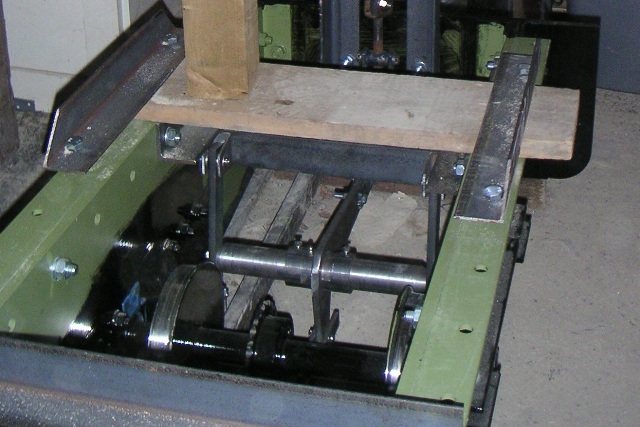
Brake crank at No.2 end - the timber work and sawdust is from a temporary seat.
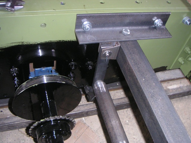
Brakes at No.1 end.
At the No.1 end, the brake rigging should exert an approximately horizontal force on the cross beam, but to do this the brake rigging would need to pass through both axles. A bracket, pivoted on the cross beam but fixed rigidly to the brake rigging, allows the rigging to pass underneath both axles whilst still applying a near horizontal force onto the cross beam. The cross beam is at the height it is - the same height as the cross beam at the No.2 end - to ensure that an even brake force is applied to both axles.
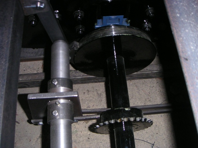
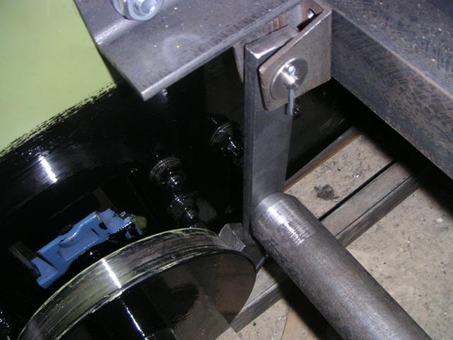
The cross beam bracket at No.1 end.
The crank is pulled up via a brake wheel on a shaft at the No.2 end, the shaft having a thread at the lower end. Originally the shaft was directly connected to an extended shaft, but the brake wheel turned the opposite way from the norm and required an inordinate number of turns to apply or release the brakes, and so an alternative scheme was devised. The traveller on the threaded end of the shaft is now connected to a rocker arm, from the other end of which a pair of drop links connect to a point a little way in from the outer end of the crank. This corrects the rotation of the shaft, and reduces the number of turns required. The threaded bar, traveller and most of the metalwork for the rocker arm and drop links came from a Morris Minor jack, obtained for the price of a pint.
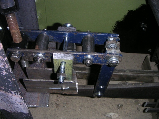
The brake rocker arm - all needs tidying up and the central pivot replacing with something more suitable.
The brake handle is made from a redundant valve wheel. The wheel was formally in use to control the starboard engine LT cooler sea water outlet in the engine room of a Rolls Royce UT775L supply ship.
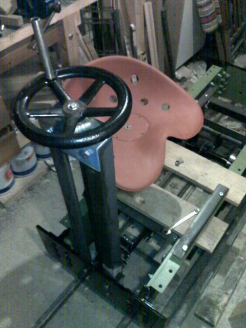
The brake wheel - the frame is 50 x 50 angle and the shaft is 25mm bar. The seat is new - bought from a tractor spares dealer - and is currently mounted on a temprary timber frame.
Brake test
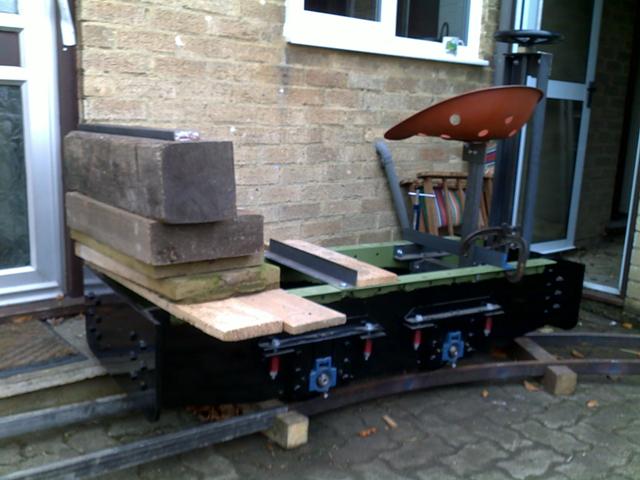
End of October - Conducted a brake test to see whether the whole thing worked or not. After a few issues arising from the uneven weight distribution caused by me sitting on one end and the Lister engine (which should be at the other end) still sitting in the garage, it was fairly successful. I had to perch in the middle rather than sit on the seat to stop the no.1 end (engine end) wheels from locking up, but this should be corrected once the Lister is installed. I was able to control the descent on the steepest section pretty well, and this should get better once the brake blocks are worn in.
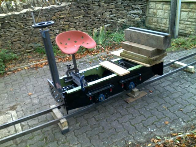
This shows the loco on the temporary track - gradient was 1 in 8. The concrete slabs and wooden blocks are trying to emulate the weight of a Lister D.
This shows the loco at the bottom of the temporary track - still in once piece.
A short video of one of the brake test runs, courtesy of the WLR's official cameraman - wmv format and about 4Mb.
March 2010 - All the brake rigging has been dismantled and painted, and most of it has been re-assembled again. Still need to paint the brake wheel support, and I can't finish re-assembling the brakes until I've done that. Meanwhile, a start has been made on the Lister.
End of April 2010 - Been away, including a week at Wernigerode in the Harz Mountains. Thoroughly recommend Busche's Eis - beer, ice cream and coffee (not necessarily in that order) - all within sight of the Harz Railway's Wernigerode shed and right next to their running line. Very impressed with some of the HSB's motive power, although not sure how to adapt a 2-10-2 for minimum gauge on 10 1/4 inch!
Whilst enjoying the HSB, did some cogitating on the brakes. I'm not happy with the way the rocker arm is sat on top of the support arms - it's basically unstable, with the downwards force that is being applied by the brake column and the crank being converted into a significant horizontal force onto the threaded section of the brake column. My plan is to suspend the rocker arm from above, so that the downwards force tends to centralise it rather than trying to force it off-centre.
Start of May - Just had a look at rearranging the supports for the rocker arm, and have now remembered all of the reasons why I did it that way in the first place! Have decided to stick with the status quo. Have added a brass bush to the lower bracket where the bottom of the brake column comes through. All of the brake gear now back together again.
Build part 3 - engine and transmission
